Thursday, December 6, 2012

Procedural Castle


I've been taking a break from trying to synthesise natural terrain features and instead been working on a system to create buildings in a procedural manner.  I've looked a little at this before in my previous Osiris project (see Building Placement Revisited) but didn't take it much further than producing some roughly textured boxes:
Simple skyscraper buildings produced procedurally
I thought it was about time I pushed it a bit further to produce structures to make my new voxel worlds a bit more interesting.  I've taken the basic system I was developing before but reworked and extended it to make it more powerful and capable of producing more varied output:
Voxel castle produced by the new procedural building system
It's not exactly going to win any modelling awards but I'm hoping the mechanism behind it's production will give me the power to create all manner of man made structures and buildings reasonably simply.

The system is inspired primarily by the work of Müller, Wonka, Haegler, Ulmer and Van Gool in their paper Procedural Modeling of Buildings where they present a grammar based system for the specification of buildings (See Miguel Cepero's Procedural World blog for another interpretation of this work), this essentially enables a set of rules to be written which when interpreted by a parser results in geometry being created representing the building for rendering.

Language Choice

I wanted the system to be easy to play with so it was essential that the runtime be able to reload and parse these rules dynamically without having to recompile or even re-run the program so coding them statically into the C++ source was out, but rather than write my own parser I decided to make use of the Lua language and integrated that into my project instead.  This gives me an out of the box solution for runtime loading and parsing and provides a far more powerful language feature set than I could hope to achieve in any home grown system.

Lua also has the advantage of being a model of simplicity to integrate with C++, syntactically similar enough to be quick to learn and well supported with documentation and tutorials on the internet.  There are even various editing environments with support such as Notepad++ and Sublime providing out of the box syntax highlighting (there is also a Visual Studio extension to provide Lua syntax highlighting although at this time it appears to not support the 2012 edition I am using).

The Fundamentals

In essence, I am representing each type of building or structure with a Lua file, when a building of that type needs to be generated the Lua file is loaded and an entry point function called "Axiom" executed.  From here on the Lua environment has control making it's entire feature set available to richly describe the shape and construction of the building. The output of this process is a Signed Distance Field (SDF, i.e. a 3D array of signed distance values) that can then be plugged in to the sparse voxel octree builder to produce a data structure the GPU ray caster can process to render images such as the castle above.

I expose a number of C++ functions to the Lua environment (22 at this time) that the script can call to perform useful intermediate processing operations and to output the final primitives that the SDF is constructed from.

The fundamental concept the script operates on at any one time is a 3D bounding box called a Scope, when the Axiom function of the script is called there are globals called xPos, yPos, zPos and xSize, ySize, zSize pre-defined with the 3D position and size of the current scope respectively which can be used to either emit an output shape or create additional scopes for further processing.  Each additional scope created is given a name which is the name of the Lua function to call to produce it's contents.  When that function is called it will in turn have the position and size globals pre-set to represent it's own position and size thus allowing each function to act on it's own area of 3D space without having to worry about where it came from or what transforms it's parents have been through.

Learning by Example

If that sounds confusing, a simple example might help:
function Axiom()
    Scope(0, 4, 0, xSize,ySize-4,zSize, "Castle");
    Scope(0,0,0, xSize, 4, zSize, "Ground");
end
here the main Axiom function is taking the original scope it's been given (which encompasses the entire 3D bounds of the building to start with) and creating two further scopes for later processing.  The first is called "Castle" and is at position (0, 4, 0) with the same size as the global scope in the X and Z axis but four metres shorter than the global scope in the Y axis.

The second scope it creates is called "Ground" and is at the origin of the current global scope (the origin is in the minimum corner of the box in (x,y,z) space) with the global scope's size in X and Z but is four metres tall in Y (the height).  Essentially this is dividing the total space of the building into two horizontal slices, a 4m tall one at the base which will become the ground and a second sitting on top of that into which the building proper will be generated.  The global scope is automatically destroyed when the function exits as it's not needed any more.

As it stands this script won't actually output anything, we need to add more code so it knows what to do with those two new scopes:
function Castle()
    Box(5, 0, 5, xSize-10, ySize, zSize-10);
end

function Ground()
    Box();
end
note here how the name of the scope is simply the name of the Lua function to call - a great advantage of a dynamic language like Lua that would be impossible in C++.  In this simple example I've made the Castle function output a box 10m smaller than but centred within the scope in the X and Z axes and the full height of the scope in Y while the Ground function simple creates a box that fills the scope.

Note the handy shortcut for the ground's box - having a shape fill the current scope is a common requirement so overloadings of many functions such as Box are provided that assume the origin and scope size as defaults.

Running this simple script now produces this:


not perhaps the most convincing of castles but hopefully you can see how the script produces what you see here.  It's important to remember though that it's not geometry that's being generated - there are no vertices and triangles being created by that Box function; instead for each point in the 256x256x256 SDF grid I'm using in the viewer it's calculating how far that point is from the surface of the boxes and storing that.

The brick and stone texturing is a result of the default appearance set when scripts are run, appearances are essentially a pair of textures one of which is used for flat surfaces and another for vertical ones - surface in between receive a blend of the two textures depending on their slope.  It is possible to specify different appearances when creating shapes but I'll let these examples stick to the default for now.

A Slightly More Complex Example

I don't want to turn this post into a reference manual for the construction system as that would be quite verbose and probably not terribly interesting so I'll jump straight forward to a more advanced example, making a tower with a crenelated top:


and here is the code that produced it:
function Axiom()
    Scope(xSize/4, 4, zSize/4, xSize/2,ySize-4,zSize/2, "SquareTower");
    Scope(0,0,0, xSize, 4, zSize, "Ground");
end

-- Produces a square tower with a crenelated top
function SquareTower()
    Box(xSize, ySize-3, zSize); -- Body of square tower
    SquareBoundary(merlonDepth, ySize-3, 3, xSize, zSize, "WallRampart");
end

-- Produces four long thin scopes forming a square boundary edge
function SquareBoundary(thickness, yPos, height, xSize, zSize, scopeName)
    Size(thickness, height, zSize);
    Scope(0, yPos, 0, scopeName);

    RotateToY(180);
    Scope(xSize, yPos, zSize, scopeName);

    Size(thickness, height, xSize);
    RotateToY(90);
    Scope(xSize, yPos, 0, scopeName);

    RotateToY(270);
    Scope(0, yPos, zSize, scopeName);

    RotateToY(0);
end

-- Produces a low wall topped by crenelations
function WallRampart()
    Box(xSize, ySize*0.5, zSize);

    Size(xSize, ySize*0.5, zSize+crenelWidth);
    MoveTo(0, ySize*0.5, 0);
    Appearance("StoneWall");
    SubDivZ({ "rep", merlonWidth, "Merlon" });
end

-- Produces a single merlon
function Merlon()
    Box(xSize, ySize, merlonWidth-crenelWidth);
end

hopefully it's length doesn't scare you off, assuming you're still with me you can see that the basic structure is the same; functions are often creating new scopes at a given position relative to their parents and based on the parent scope's size.  Points that I think are worth noticing include:
  • The SquareBoundary() function shows how other Lua functions can be called just like normal to do additional work and allow code re-use without having to create intermediate scopes
  • The RotateToY() function demonstrates rotating scopes, all translation and rotations are inherited automatically to child scopes
  • The Appearance() function is used here to change the appearance for subsequent shapes, in this case changing to an appearance that doesn't have the rock floor texture so we don't get rock on the flat top surfaces of the merlons.
  • The SubDivZ() function illustrates a more powerful way of subdividing space, in this case creating as many instances of the Merlon scope with a given width as will fit along the Z axis of the current scope.
Constructive Solid Geometry

At the moment the system is only capable of generating two basic geometric solids from it's scopes, either the boxes you've already seen or cylinders along the X, Y or Z axes.  These basic shapes can be combined however to create far more interesting shapes using a technique called Constructive Solid Geometry (CSG) where the results are combined using one of a range of boolean operators.

There are three primary operators available:

Union is the default which merges the shapes together
function Axiom()
 Box(0, 0, zSize/4, xSize/2, ySize/2, zSize/2);
 CylinderZ(xSize/4, 0, 0, xSize/2, ySize, zSize);
end
Subtract removes the second shape from the first
function Axiom()
 Box(0, 0, zSize/4, xSize/2, ySize/2, zSize/2);
 CylinderZ(xSize/4, 0, 0, xSize/2, ySize, zSize, CSG_Subtract);
end
Intersect produces the portion of solid that is common to both
function Axiom()
 Box(0, 0, zSize/4, xSize/2, ySize/2, zSize/2);
 CylinderZ(xSize/4, 0, 0, xSize/2, ySize, zSize, CSG_Intersect);
end

CSG has been around for a long time and I've used it before on CPU based ray tracer projects where it's relatively straightforward to implement operating on the intersecting spans of rays, but it's a whole lot more complicated when operating on geometry as the finite numerical precision of floating point numbers often leads to problematic fragments and slivers of geometry, problems with non-sealed hulls and issues with coincident surfaces.

Dealing with SDFs however eliminates these problems as the sample space is regular with no problems of open or closed surfaces.  (See Iñigo Quilez's page on Modeling with Distance Functions if you are interested in this)

In addition to the regular boolean operators, working with SDFs provides some other interesting options:

Adding signed distances together to create a blend
function Axiom()
 Box(0, 0, zSize/4, xSize/2, ySize/2, zSize/2);
 CylinderZ(xSize/4, 0, 0, xSize/2, ySize, zSize, CSG_Add);
end

here a basic addition is being applied resulting in a blend between the box and the cylinder shapes, likewise subtraction and other arithmetic operations can be used.

Advanced Parameters

The flexibility of Lua also makes it simple to add additional optional parameters to function calls.  By allowing a table to be passed at scope and shape creation time context specific values can be given:

CylinderY(0, ySize-10, 0, xSize, 10, zSize, { topRadius=0; appearance="RoofTilesBrown" });

here the cylinder has been given a zero top radius factor to turn it into a cone and the appearance for the shape changed to a brown roof tile effect producing the top of the castle's turret:

Turret roof formed by a cylinder with zero top radius
Space Modifiers

Finally it's also perfectly possible to apply arbitrary functions to areas of the SDF in much the same way as the geometric primitives do, but instead of generating values we can modify the values already present to produce interesting or bizarre effects that would be difficult to achieve with geometry directly (or at least without massively tessellated geometry)

NoiseShape(-4, -4, -4, xSize+8, ySize+8, zSize+8, CSG_Add, { noiseScale=0.5, noiseAmplitude=1.5 } );

here a Noise modifier has been applied to an area of the scope to warp the values already generated for the keep:

Regular keep without the modifier applied
Same keep with the Noise() modifier applied just for fun
although this is something of a contrived example (unless you were planning on making a castle out of jelly) it shows the power of the effect, other effects such as twists, warps and even softening blurs are also possible.

Variations on a Theme


So far everything presented here has been undeniably procedural being based on rules and parameters but it has also been entirely deterministic.  If I feed one of these Lua scripts into the system five times I will get exactly the same building out each and every time which is going to make it somewhat tedious to produce the wide variety of buildings and structures with which I hope to populate my voxel worlds.

The real power of procedural systems though of course is their ability to produce endless variations of something by supplying different input parameters or seeds.  For my building system there are only two primary inputs that dictate how the final architecturee looks: the first is the bounding box for the building comprised of the size of the plot onto which the building must fit and the height it's allowed to reach.  These would be defined by the higher level town or city planning systems driven by factors such as population density, building type and the distance from the centre of the conurbation, the bounds are simply passed to the Axiom function as the size of the root scope.  By writing the Lua script properly it can be made to work with a wide variety of overall building sizes, functions such as SubDiv() are really useful here to enable repetition along unknown length regions without undue scaling or stretching.

The second factor that has a more significant impact on the form of the building is the seed value that is used to initialise the random number generator.  This is calculated from the position of the building on the planet so the same building in the same spot will always look the same but the same script file used to generate a building at a different location may look completely different.  The Rand() function is used in the script to make decisions that can change the architecture: deciding whether to put a square tower, a round turret or nothing at all on a corner of the castle for example or whether there is a gateway on a given wall.  Rand() can also be used to vary the size of scopes and shapes, so for example once the choice of tower or turret is made it's width and height can be further randomised within sensible limits leading to a wide variety of final apperances.


Wrap Up

Hopefully this has been an interesting glimpse into what I hope will be a powerful system for synthetic formations, I've certainly learnt a lot about Lua and it's integration with C++ along the way which has been rewarding in itself, but feeling like the system I've created is open and flexible enough to produce interesting, realistic(ish) or even fantastical structures is satisfying.

There is even scope here to release a stand alone version of the viewer tool these screenshots are from so you too could experiment with creating architecture from Lua - as long as people can accept it's limitations of course

Anyone interested?

Thursday, November 8, 2012

Impossible Worlds

Although I was pretty happy with the DEM terrain mapping described in my last post, I was aware that it didn't exactly show off the incredible flexibility that moving to voxels provides over the more traditional height-field grid techniques I employed in some of my previous projects.  You pay a massive cost in complexity, computational cost and rendering performance moving to voxels so it seemed a bit poor to not show off their strengths a bit more.

To this end, and just to have a bit of fun, I've been playing about with the underlying distance field functions my planets are based upon.  All the images in the previous post used a simple spherical distance function to give a basically realistic planet shape, but there's absolutely no reason (discounting physics) not to use any arbitrary function to produce the underlying shape upon which the DEM mapping works.

Here are a few of the toy-worlds I came up with:
Why not have a cube world...
  (maybe the birthplace of the Borg?)

Or a torus?
A union of three cylinders with a bit of -ve blending at the intersection
...and my timely tribute to Halo 4...
Obviously the terrain system copes with varying degrees of success when applied to these unconventional shapes but considering that it was designed for spheres it's surprisingly decent.  A proper parametric mapping would work better for the shapes that have one but these experiments are just toys after all.
Blobby world based on a low frequency noise function
Although the plan is for planets in my universe to be in general constrained by the laws of physics and nothing like these, this generality of form opens the door for having blasted husks of planets with huge chunks missing, cracked open meteorite ravaged planetoids and maybe just the odd eccentric alien world...

Tuesday, November 6, 2012

The Birth of Voxel Planets

After getting some basic data sets up and rendering with my GPU based sparse voxel octree ray-caster I wanted to get stuck in to actually using it to render planets.  Now as I've discussed before planets are pretty big and dealing with them can throw up many numerical precision issues for algorithms.  Having dealt with these in past projects however it seemed daft to reinvent the wheel so I spent some time porting the general solar system simulation code from Osiris into Voxelus.  This was made more complicated and time consuming as I started a whole new C++ framework for Voxelus rather than use what was becoming a very old and messy utility library - it was time well spent though as I believe it's healthy to have a clean slate now and again.
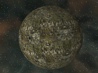
Very first voxel planet (256^3 grid)
With that done though I could bring across the procedural nebula backdrop generator which with a couple of colour tweaks just for fun at least gave me a nice cubemap backdrop.  Above is my very first voxel planet, rendered using a 256^3 data set as source for the SVO with tri-planar texture mapping to give it some interest.  The distance field from which this is generated is really just "distance from surface of sphere" so it's neither particularly interesting nor showing the power of voxels, but it's a start.

Modelled as an earth side planet, the 256^3 data makes each voxel almost 50 Km on a side!

Now perfect spheres can only be so interesting, so adding some relief detail was my next job.  Although completely arbitrary shapes are possible with voxels I wanted to get started with some fairly traditional planet forms so the initial focus was on producing something reasonably realistic.  I've used a variety of fractal functions in the past to simulate terrain, ridged multi-fractals being a popular choice but such terrains tend to suffer from a large degree of homogeneity - they tend to have a large degree of self-similarity especially across large areas even when combining numerous frequencies.

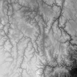
In the spirit of trying new things, rather than tread that worn path again I wanted to try something different for Voxelus.  Rather than generate heightfields from fractals, I wanted to see if I could generate something suitable using real-world Digital Elevation Model (DEM) data.  A little searching turned up the Shuttle Radar Topography Mission (SRTM) data which is available in a variety of resolutions.  Downloading this and writing a little command line tool to load and cut out interesting sections of it enabled me to produce a library of DEM tiles that I could use.

Two examples of DEM patches my tool cut out of the massive SRTM 500m data set
I used a simple height histogram to choose areas where there was a lot of variety in elevation in an effort to make the final result more interesting - although the SRTM 500m data set is hundreds of MB in size, a surprising amount of the Earth's surface is in fact pretty damn flat!

Armed with my library of DEM tiles I needed a way to map them onto my planet.  Mapping 2D squares onto a sphere is however a classically impossible task (ask any cartographer) so rather than being able to make some perfect mapping I instead needed to quilt the surface with overlapping tiles, using as few as possible while ensuring that there were no gaps in between. I also wanted to be able to quilt at various resolutions so I could combine several "octaves" of DEM data in a traditional fractal-esque fashion.

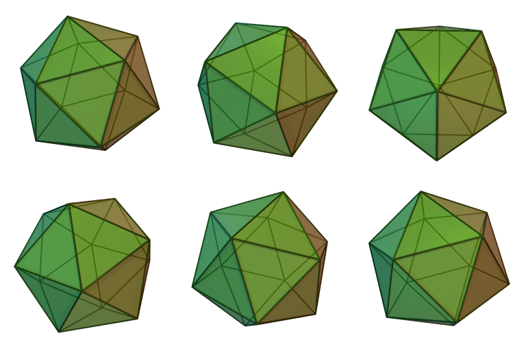
To do this, I based my mapping on an Icosahedron, a regular polyhedron made up of 20 triangles.

Icosahedron (image from Wikipedia)
The key attraction of the icosahedron is that each side is an equilateral triangle producing an even distribution of surface area, and that each side can be recursively subdivided into four smaller equilateral triangles to produce higher and higher detail meshes with the same characteristic.  By normalising the position of the vertices introduced by these subdivisions an increasingly high quality approximation to a sphere is achieved.

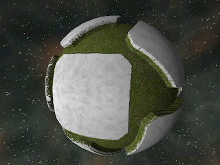
To map my DEM tiles onto the sphere I treat each triangle of the icosahedron as representing one tile.  The centre of the tile lies on the centroid of the triangle and extends outwards to cover the triangle completely.  Each tile also has a random rotation around the centroid so to ensure that there are no gaps between the tiles from adjacent faces, the tile has to be twice the radius of the triangles circumscribed circle in size.  There will be considerable overlap around the edges between adjacent tiles but that's all the better to avoid seams.
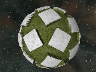
First "octave" of DEm tiles at primary icosahedron vertices, there are 12 tiles here

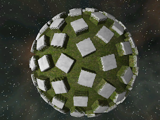
One further level of subdivision produces 42 smaller tiles

Subdividing again produces 162 even smaller tiles
These three images are to visualise how the tiles are distributed on the sphere. These examples actually have the tiles at the vertices rather than the triangle centroids but I later switched to the centroids as I thought it gave a better result.  Centroidal tiles produce 20, 80 and 320 tiles at each level respectively.  The tiles here are artificially smaller than final size simply to improve the visualisation.

Expanding the tiles to their correct sizes and repositioning them at the triangle centroids rather than the vertices produces a more accurate result:


Here the individual tiles have been tinted to aid identification and the edges shaded green based upon the weight of their influence at that point.  As you can see the weight of each tile fades off towards it's edges to avoid hard seams and there is no space between them regardless of their orientation to ensure a complete mapping of the sphere.  I've added a simple directional light so the relief from the DEM data can be seen.
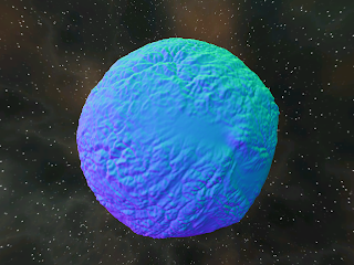
Normals from just the basic level #0 data
Here the voxel normals can be seen, note that this is using just the 20 tiles from the level #0 quilting but with a  mountain height of about 500 Km to make detail obvious from such a distance - by comparison Mt. Everest on Earth is just 8.8 Km tall.

Finally here is the same level #0 data with some basic elevation/slope based texturing applied.  Even with just one level of DEM data I am quite pleased with the appearance of the terrain, particularly with the variety of landscape forms in evidence which encourages me that this technique might just be viable.

The coarse 256^3 nature of the data can be quite clearly seen in this image even from this distance so I think starting work on the dynamic resolution subdivision system for closer views might be next on the list of things to tackle.

Sunday, October 7, 2012

Sparse Voxel Octrees: A New Beginning


There’s been quite a lot of interest lately in the realtime graphics world to do with Sparse Voxel Octrees (SVOs), so I thought it was about time I had a look at them.  Although I’ve experimented with voxels before, in particular in the Geo project I worked on a few years ago (http://jwhigham.wordpress.com/category/geo) I didn’t really make use of octrees in those cases and more significantly I converted the voxel data to geometry prior to rendering using the classic Marching Cubes algorithm - now generally superseded by better techniques such as Dual Contouring.

Having been down that route before I wanted to try something new so this time I’m endeavouring to render by ray-casting directly against the SVO rather than converting to geometry and rasterising.  I don’t believe that ray-casting (or ray-tracing if you want to consider more than one bounce) is going to replace rasterisation any time soon as the genesis of GPUs has left them understandably specialised for that particular problem and therefore very efficient at it.  I do believe however that when used in conjunction with rasterisation ray casting or tracing is a tool too powerful to ignore and can be an ideal solution for effects such as reflection, refraction, shadows and global illumination that are difficult to simulate with rasterisation, especially at a global scale.

128x128x128 SVO ray-cast on the GPU with simple dot-product lighting
There have been numerous articles published in recent years postulating that rasterisation is dead and raytracing is the next big thing and just as many countenancing the opposite, the truth of course as I see it is somewhere in the middle – both have compelling strengths and weaknesses so surely the best solution is to combine them, using each where best suited to maximise their strengths.

So while it’s technically perfectly possible to convert the voxels to geometry and then intersect rays against the resulting polygonal soup it flies in the face of this belief and doesn’t strike me as a particularly sensible thing to do.  I also want to see if ray casting against the voxel structures directly can help alleviate some of the more challenging problems with geometry based voxelisation, particularly transitions between multiple levels of detail which I struggled with on Geo.  Also like I say, it’s not something I’ve done before which is really reason enough.

128x128x128 Sphere rendered with linear distance filtering

The same sphere rendered with point distance sampling to make the individual voxels clearer
The Aim

Ultimately I would like to recreate my virtual planet out of landscape blocks of varying resolutions right down from global scale viewed from orbit to standing on the surface with reasonable fidelity.  I’ll also need to have a think about how to procedurally generate the data as the flexibility to have full 3D makes the problem far more interesting than just the heightfield used by Isis (http://jwhigham.wordpress.com/tag/isis/) and Osiris (http://johnwhigham.blogspot.co.uk/search/label/Osiris).  I want to avoid if possible having the floating blobs of landscape that plagued Geo’s simplistic 3D noise based solution while still having features that make the 3D nature of the data obvious such as realistic overhangs and caves.

First Steps

As with most new experiments the first thing to do is investigate the existing body of work on the subject, which as I mentioned earlier is quite active at the moment with the dramatic increase in GPU performance and especially their flexibility in recent years.  See the references section at the end for a few links to papers and videos I discovered in my internet SVO safari, it’s by no means an exhaustive list but they are some of the more interesting items I found.

Once I felt I had a sufficient understanding of current techniques I jumped in with both feet and embarked on a bit of coding.  While the aim is to produce a real time GPU based solution my experience of the somewhat patchy tools available for GPU debugging steered me towards producing a reference implementation in C++ on the CPU first.  While it would run far more slowly this would let me debug the code effectively and help me verify that my algorithm and data structures were correct before sending them down to the GPU.
This turned out to be a really useful process and with modern CPUs being pretty powerful themselves (and ray casting being a parallel friendly technique) it was possible to produce a C++ implementation that ran acceptably quickly even in debug builds.  Having it render a quarter resolution version during camera movements and a full resolution one once the camera stopped also helped.

The first technique I attempted was the Laine & Karras one.  While there was sample source code available for this I am of the belief that to properly understand a technique you have to at least have a go at coding it up from first principles so that’s what I did.  After a while though my spider sense started to tell me that storing down to the individual voxel level wasn’t going to be best suited to planetary scales so I switched to the Cyril Crassin paper where he stores an octree down to a certain level then stores bricks of voxels rather than individual ones for the final few levels.

The 16x16x16 grid of voxel "bricks" that make up the actual Octree
The algorithm traverses the octree until it arrives at a suitable level of detail or a leaf node then ray-marches through the chosen brick (8x8x8 in my implementation) to find the accurate intersection.  Written well it's trivial to alter the size of the bricks to compare performance and memory use in different configurations.

This system felt more scalable and better suited to GPU application, plus there were advantages to do with cone tracing through the structure for shadows and global illumination applications that felt worth having available for the future.

Storage

It’s pretty clear that a voxel is a cube shaped blob of space, games such as MineCraft have made the voxel pretty famous these days, but there are a couple of key considerations when rendering them.  Primarily is what each voxel represents, in it’s most simplisitic form a voxel could be considered to be either solid or empty which is easy to understand but limits rendering to producing blocky effects dependent entirely on the size of the voxels in use.  Rather than storing a flag indicating solid or empty with a voxel a better way is to store a distance value representing how far the centre of the voxel is from the surface that is to be rendered.

Under this representation for a landscape voxels above the ground would have increasingly positive values while those underground would have increasingly negative ones.  Rendering the isosurface where the distance is zero would produce the intended surface.  The primary benefit of this scheme is that the distance value can be interpolated accurately between voxels to produce a better approximation of the surface.  The quality of the output is still highly dependent upon the resolution of the data but undersampling artifacts show up as lumpy blobs rather than hard square edges which I think look generally better.

The images below show the progression from highest detail to lowest through the four levels of octree produced by my 128x128x128 noise-blob data.  Note that I've turned off the linear filtering of distance here in all but the final image to make the individual voxels clearer:

The 128x128x128 noise-blob at octree level 4 (highest detail)
The same 128x128x128 blob at octree level 3, each voxel is effectively twice the size
Down to octree level 2 and while the shape remains the detail is largely gone
Finally at the lowest detail level on the crude outline remains.  The 128x128x128 original data  is now effectively being rendered at 16x16x16 resolution.
The same lowest detail level but with linear distance filtering - not a terrible approximation of the blob considering it's only using 1/512th of the data
Normals for shading and procedural texturing can either be pre-calculated and stored in the voxels or calculated at runtime from the gradient of the distance field – empirical testing will show which is faster in practice although my current thoughts are that it's probably better to store higher precision distance values and calculate the normal when needed.  Although many steps are taken through the distance field only the normal at the closest intersection is needed so it only needs to be calculated once before shading.

On top of the distance value there are also other required fields such as material types which I have some ideas for but I’ll get in to that in later posts.

From CPU to GPU

Once I was happy that everything seemed to be working on the CPU I set about converting the code to run on the GPU using a pixel shader.  I toyed briefly with using a compute shader instead as I've heard there are some benefits to converting some traditionally pixel based tasks to the more flexible compute pipeline but I'll save that for a rainy day.  Ray casting seems a natural fit for per-pixel so I'm sticking with a pixel shader for now.

Thankfully as it had always been my intent to run it on the GPU I had written it with that in mind so storing the data structures in textures and moving the code to HLSL was fairly straight forwards.  It did take a few hours to work out the inevitable teething problems compounded by the typically unstable nature of GPU debugging tools but considering what it's doing it didn't take too long.

The benefit of course is that instead of taking a couple of hundred milliseconds to render it now rendered in just a few milliseconds giving me true real-time frame rates.  Being able to dynamically reload the HLSL code and GPU states also meant I could make changes and see the results virtually instantly without having to re-run the program, saving a considerably amount of time.  If you are creating a graphics framework for your own projects I strongly recommend adding this ability!


Two-sphere distance field showing the geometry that is actually sent to the GPU (i.e. 12 triangles).  The back-faces of the cube are rendered instead of the front to allow the viewpoint to move inside the cube and still render
Next Steps

So I have a single sparse voxel octree I can render via ray casting on the GPU complete with surface normals, what's next?  Well the first thing to do is to be able to render multiple SVOs at different points in space, also to have them abut neatly with continuous surface normals so there are no shading seams.

After this I want to add some automatic level of detail control so the tree is traversed less deeply as the voxel bricks become smaller on screen, having this controllable from the user interface would also be useful to allow performance to be measured against visual fidelity.  Next I want to add a new distance generation function to produce blocks that are a bit more landscape-like plus having the materials to go with them.

So, plenty to do then!

References:

As mentioned above, this is a fairly arbitrary collection of some of the links I came across while researching SVOs.  I am sure there are many more so do feel free to report any good ones you find in the comments!

http://www.tml.tkk.fi/~samuli/publications/laine2010tr1_paper.pdf
Efficient Sparse Voxel Octrees – Analysis, Extensions, and Implementation, Samuli Laine Tero Karras, NVIDIA Research

http://en.wikipedia.org/wiki/Sparse_voxel_octree
Sparse voxel octree

http://www.daimi.au.dk/~aquak/MasterThesisKristofRoemisch.pdf
Sparse Voxel Octree Ray Tracing on the GPU, Kristof Römisch, Masters Thesis

http://maverick.inria.fr/Publications/2011/Cra11/
GigaVoxels: A Voxel-Based Rendering Pipeline For Efficient Exploration Of Large And Detailed Scenes, Cyril Crassin, PhD thesis

http://www.youtube.com/watch?v=VpEpAFGplnI
Sparse Voxel Octree (SVO) Demo by Jon Olick

http://procworld.blogspot.co.uk/
Procedural World

Wednesday, May 2, 2012

Links, old and new

I thought people with similar interests to myself might find these recent presentations interesting:


I also came across a commercial terrain tool I wasn't aware of:


and finally just for fun here are some retro links to some information on "White Magic 1" & "White Magic 2" - the very first games I had commercially published:


This was on the Acorn Electron back in 1990, 1 whole Mhz of 8bit power and 32K of total RAM driving a 160x256 screen resolution with four colours and a tape drive!

I couldn't afford a floppy disc drive at the time so had to assemble the code to the screen memory, save the assembly source to tape then copy the machine code from the screen memory into normal memory to run it before loading the graphics from tape each time I wanted to test anything...happy days.

Thursday, April 5, 2012

24 Hours is not enough


It's been a while since I posted any progress updates about the Osiris project, what spare time I have has been fairly thoroughly sabotaged this year so far by the double whammy of receiving Skyrim for Christmas then just as my interest in that was waning Mass Effect 3 coming out.  Instead of working on shaders and infrastructure generation I have therefore instead been largely sneaking up on bandits & dragons and battling the Reapers in deepest space.

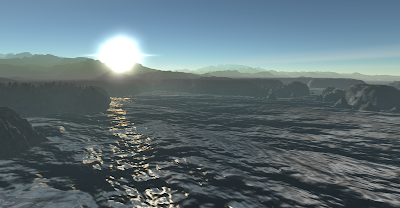
I love playing games and I love working on interesting software projects...but it would seem that there just aren't enough hours in the day to do both.  Having said that I have managed to devote some time here and there to Osiris and have been primarily working in two areas: working on implementing a new and more flexible texturing solution for the terrain and adding oceans and other bodies of water.  I plan to produce more detailed posts describing my experiments in these areas in due course but for now I thought I would whet the appetite a little with a couple of screens from the water experiments.

Although I've done deep water simulation on previous projects (Isis) using a 64x64 FFT grid processed on the CPU, I wanted to try a more modern approach with Osiris so took inspiration from an NVIDIA demo and have implemented a 512x512 FFT using Compute Shaders to do the heavy lifting.  This produces a height field, gradient and folding maps that are then fed into the vertex and pixel shaders.  The effect is best suited to deep water so works well for oceans - rivers and smaller pools will need something else.

Like I say I'll go in to more detail later, but for now here are the screens - I'm particularly happy with the way the effect scales into the distance which requires a little work to stop the FFT grid visibly tiling:


Wednesday, March 7, 2012

Outerra Tech Demo Download

I recently found out that the impressive Outerra project now has a technology demo that can be downloaded to interactively play around with their system.

I've been following the Outerra project for a while now and the guys there are doing some really inspirational work.  I strongly recommend checking it out if you are at all interested in real-time virtual worlds - even though it does make my own humble efforts look somewhat less stellar :-)


Monday, February 27, 2012

The Scale of the Universe

Just a short note this one to point out a link I find very interesting.  Entitled "The Scale of the Universe" by Cary Huang it's a fascinating interactive exploration of the relative sizes of all manner of entities in the Universe.

The Scale of the Universe

Maybe it's just me, but I find zooming in and out and clicking on the different entities for extra information strangely compulsive...

Wednesday, February 22, 2012

Understanding BCn Texture Compression Formats

Texture compression can be something of a black box with many people happy to just "turn it on" to save memory or increase performance and think little else about it, but in practice the different DXT compression formats that have been available in DirectX for years have significant behavioural characteristics that can make a radical difference to the visual quality of a project.

More recently DX10 and DX11 have brought in even more choice with the replacement of the DXT formats with no less than seven flavours of block compression, conveniently known as BC1 to BC7 making the choice of texture storage format even more significant to achieve best quality visual results.

While the DirectX documentation on these formats is technically rich, it's not the clearest introduction to the formats and doesn't always make it clear which is best for what purpose and why - fortunately though graphics programmer Nathan Reed has kindly taken the time on his blog recently to fill that gap with a clear explanation of the different BC formats.

So if you are interested in texture compression or just want to make sure you're making the most of your carefully crafted  DX10/11 project's visuals I suggest giving his excellent article a read:

Understanding BCn Texture Compression Formats

Wednesday, February 8, 2012

More on Floating Point Precision

I read an interesting article on the excellent #AltDevBlogADay site the other day entitled "dont-store-that-in-a-float" - a brief but clear and informative discussion on the perils of precision with single precision floating point numbers.

I would recommend a read of this to anyone experimenting with projects similar to my own as this is a key issue to the simulation and rendering of planetary and solar bodies due to the combination of immense and tiny distances that need to be represented - at times simultaneously.

Understanding how floats deal with and represent precision certainly pays dividends when trying to work out why things are clipping or popping around the screen when they really ought not to be!

Friday, January 27, 2012

Ducks and Dogs

Not a feature update today, more of a thought-of-the-day(tm):
I spent quite a few hours the other day trying to work out how a specific texture in my project was apparently being point sampled while others using the same sampler states were being tri-linear filtered as they should have been.  I tried using Pix to determine just what state the GPU was in but without much success - Pix doesn't seem to like my project very much.
This led on to much poking around and experimental changes looking for more evidence that might point to the underlying problem.  It turned out in the end however to be nothing to do with samplers or really DirectX at all – there was a bug elsewhere in the C++ code that generates the texture co-ordinates for the geometry in question which was causing it to make them offset massively from the origin, which in turn led to a catastrophic loss of precision in the GPU interpolators creating the point sampled effect I was seeing.
Usually having stupid (u,v) values causes texture wriggling or shimmering either of which would have given the game away immediately but in this particular case it happened to make the texture look perfectly stable but point sampled.
The moral?  Try to avoid myopia when tracking down bugs – just because it looks like a duck and quacks like a duck doesn't necessarily mean it really is a duck - it might just be a dog.